Technical Support
Processing Guide
Note: The processing guide should be used as a reference only. Some adjustment might be needed, depending upon a product design and ambient conditions.
Pre-drying
Polycarbonate resins absorb approximately 0.2% of moisture at a room temperature.
Absorbed moisture can cause degradation of properties during the moulding process.
Before moulding, the pellets should be dried in a dryer to a moisture content of less than 0.02%.
Tray dryer with hot air system: For more than 4 hours at 120°C with the layer of pellets in trays not higher than 3 cm.
Hopper dryer : Keep the inlet air temperature at 100 ~ 120°C to avoid reabsorption.
Injection Molding
| Grades | Cylinder Temperature [℃ ] | Mold Temp [℃] | Injection Pressure (kgf/cm2) | Injection Speed | Back Pressure (kgf/cm2) | Screw Rotation Speed (rpm) |
|||
| Nozzle | Front | Mid | Rear | ||||||
| K-20/30/40 K-(20/30/40)MRA K-(20/30/40)UV K-(20/30/40)UVR K-30FR KFN-30 | 250 ~ 290 | 270 ~ 300 | 270 ~ 300 | 270 ~ 300 | 75 ~ 100 | 500 ~ 1800 | Mid ~ High | 50 ~ 100 | 40 ~ 80 |
| KG-(10/15/20/30)MRA KGN-(10/15/20/30)MRA KG-30F15 K-30CF10 | 280 ~ 300 | 290 ~ 310 | 280 ~ 300 | 270 ~ 300 | 80 ~ 120 | 500 ~ 1500 | Mid ~ High | ~ 100 | 40 ~ 80 |
| RS-1340 | 310 | 310 | 300 | 290 ~ 300 | 130 ~ 150 | 300 ~ 1000 | Mid ~ High | 0 ~ 10 | 40 ~ 100 |
Chemical Resistance
下表显示了聚碳酸酯树脂对一些常见化学物质的耐性。
聚碳酸酯树脂通常在弱酸环境下稳定,但会在碱性和芳香性环境下降解。
以下每种化学物质的耐性是在23°C下测试的,在较高温度下会有所不同。
| Injection Molding | Res. | Organic chemical | Res. |
| Hydrochloric acid (10% solution) | ◯ | Acetic acid (10% solution) | △ |
| Nitric acid (10% solution) | ◯ | Acetone | × |
| Sodium carbonate (saturated solution) | △ | Benzene | × |
| Sodium chloride (saturated solution) | ◯ | Benzine | × |
| Sodium hydroxide (5% solution) | △ | Chloroform | × |
| Sodium sulfide (saturated solution) | ×,Carbon tetrachloride | × | |
| Sodium sulfonate (saturated solution) | ◯ | Ethanol | ◯ |
| Sulfuric acid (10% solution) | ◯ | Ethyl ether | × |
| Methanol | △ | ||
| Tetrahydrofuran | × |
||
| Toluene | × |
||
| Plasticized PVC | × |
||
| Oil/Thinner | Res. | Detergent | Res. |
| Brake fluid | ×,Alkaline detergent | △ | |
| Engine oil | ◯ | Mild acid detergent | ◯ |
| Diesel oil | △ | ||
| Gasoline | ×, | ||
| Grease | ◯ | ||
| Kerosene | △ | ||
| Machine oil | ◯ | Food | Res. |
| Silicone oil | ◯ | Butter | ◯ |
| Turpentine oil | ×,Vegetable oil | ◯ | |
| Paint thinner | ×,Wine | ◯ | |
| Wax remover | △ | Whiskey | ◯ |
化学耐性
◯ : 良好 △: 尚可 × : 差
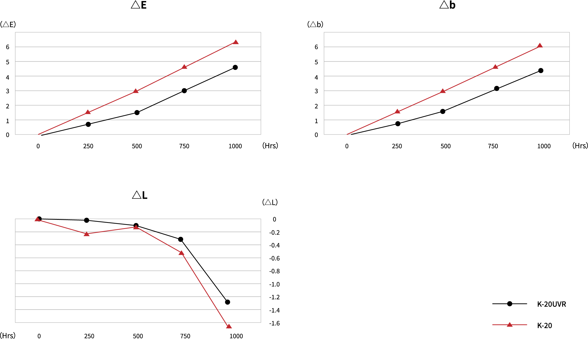
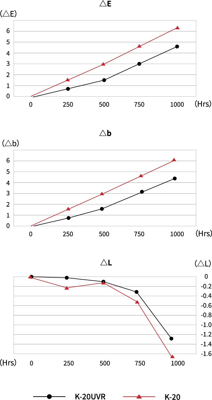
Weather Resistance
The table below shows the comparison data on K-20 vs K-20UVR in the accelerated weathering test.
Xenon Weather Meter : Suga Test Instrument XEL-7X-LHP model
Spectral Irradiance : 380
Exposure Time : 1000Hrs
Accumulated Spectral Irradiance : 136680KJ/m=380000
Black Panel Temperature : 63°
Humidity : 52%RH
Light Source/Angle : D65/10°
| 250Hrs | 500Hrs | 750Hrs | 1000Hrs | |||||||||||||
| L | a | b | △E | L | a | b | △E | L | a | b | △E | L | a | b | △E | |
| K-20UVR | 0.0 | -0.2 | -0.7 | -0.8 | -0.1 | -0.7 | 1.6 | 1.7 | -0.3 | -0.8 | 3.0 | 3.1 | -1.3 | -0.8 | 4.3 | 4.6 |
| K-20 | -0.2 | -0.5 | 1.5 | 1.5 | -0.1 | -0.9 | 2.9 | 3.0 | -0.5 | -1.1 | 4.5 | 4.6 | -1.7 | -1.1 | 6.0 | 6.3 |
Troule Shooting Guide
01. Black Specks
- 1. If a different type of the polymer had previously been used, purge it from the barrel completely.
- 2. Purge the material previously used when the molding machine is left unused over an extended time period.
- 3. Decrease nozzle temerature.
- 4. Check temperature at feed zone. Low temperatures may cause mechanical degradation, especially with high screw speed or high back pressure.
- 5. Check heater band and thermocouple location. The heater band may run at a higher temperature than the thermocouple indicates.
02. Brittleness
- 1. Dry material properly. Moisture percentage greater than 0.02% can cause a loss of properties.
- 2. Improve weld-line strength.
- 3. Decrease nozzle temerature.
- 4. Check to see if the wall thickness is constant.
- 5. Eliminate sharp corners to prevent a notch effect.
- 6. If material degradation is in doubt, lower material temperature by:
- a) Lowering cylinder temperature.
- b) Decreasing screw speed.
- c) Lowering back pressure.
03. Burn Marks
- 1. Decrease injection speed.
- 2. Decrease booster time.
- 3. Decrease injection pressure.
- 4. Check venting channels for dirts/contaminants.
- 5. Improve venting of the mold. (Add vents at burned locations)
- 6. Alter gate locations and/or increase gate sizes.
04. Discoloration
- 1. Purge heating cylinder.
- 2. Check melt temperature with a pyrometer.
- 3. Lower material temperature by:
- (a. Lowering cylinder temperature b. Decreasing screw speed c. Lowering the back pressure)
- 4. Increase back pressure to improve melt homogeneity.
- 5. Lower nozzle temperature.
- 6. Shorten overall cycle.
- 7. Check hopper and feed zones for dirts/contaminants.
- 8. Cheek for proper cooling of ram and feed zone.
- 9. Provide additional vents in the mold.
- 10. Reduce residence time.
- 11. Check hot manifold for dead spots.
05. Gloss
- 1. Increase mold temperature.
- 2. Increase melt temperature.
- 3. Increase injection speed.
- 4. Increase injection pressure.
- 5. Check surface of the mold for polish.
- 6. Clean vents.
- 7. Increase venting.
06. Jetting / Worming
- 1. Decrease injection speed.
- 2. Increase melt temperature by:
- (a. Increase cylinder and nozzle temperature b. Increase screw speed c. Increase back pressure)
- 3. Increase gate size and decrease gate land length.
- 4. Modify gate location or angle : directly into wall or pin.
- 5. Avoid gating at thick section.
07. Sink Marks
- 1. Follow rib design guidelines.
- 2. Increase injection speed and pressure.
- 3. Increase injection hold time.
- 4. Reduce melt temperature.
- 5. Reduce mold temperature.
- 6. Enlarge and/or add vents to mold parting line.
- 7. Increase size of sprue and/or runners.
- 8. Increase gate size and decrease gate land length.
- 9. Relocate gate next to heavy or thicker areas.
08. Weld lines (Knit lines)
- 1. Increase injection speed and pressure.
- 2. Increase injection hold time.
- 3. Raise mold temperature.
- 4. Raise melt temperature by increasing cylinder temperature.
- 5. Vent cavity in the weld area.
- 6. Change gate location to alter flow pattern.
09. Splay marks(Silver Streaks)
- 1. Dry resin properly.
- 2. Lower nozzle temperature.
- 3. Lower melt temperature by:
- (a. Lowering cylinder temperature b. Decreasing screw speed c. Lowering back pressure)
- 4. Decreasing injection speed.
- 5. Shorten or eliminate screw decompression.
- 6. Shorten overall cycle.
- 7. Increase sprue and runner size.
10. Sticking in cavity / core
- 1. Decrease injection pressure.
- 2. Decrease hold time and pressure.
- 3. Lower mold temperature.
- 4. Increase mold closed time.
11. Stress in part
- 1. Increase mold and melt temperature.
- 2. Decrease injection speed and pressure.
- 3. Increase gate size.
- 4. Add gates and/or relocate gates.
12. Voids
- 1. Decrease injection speed.
- 2. Increase injection hold time.
- 3. Reduce melt temperature.
- 4. Increase mold temperature.
- 5. Increase gate size and reduce gate land length.
- 6. Increase nozzle size and/or runner.
- 7. Redesign part to obtain equal wall section.
13. Warpage / part distortion
- 1. Increase injection hold time.
- 2. Increase mold closed time.
- 3. Increase mold temperature.
- 4. Check gate locations and total number of gates to reduce orientation.
- 5. Redesign part to equalize wall variation in molded part thick and thin walls.
- 6. Check cooling line layout, unbalanced cooling promotes warpage.
- 7. Increase gate size.