Technical Support
Processing Guide
Note: The processing guide should be used as a reference only. Some adjustment might be needed, depending upon a product design and ambient conditions.
Pre-drying
Polycarbonate resins absorb approximately 0.2% of moisture at a room temperature.
Absorbed moisture can cause degradation of properties during the moulding process.
Before moulding, the pellets should be dried in a dryer to a moisture content of less than 0.02%.
Tray dryer with hot air system: For more than 4 hours at 120°C with the layer of pellets in trays not higher than 3 cm.
Hopper dryer : Keep the inlet air temperature at 100 ~ 120°C to avoid reabsorption.
Injection Molding
| Grades | Cylinder Temperature [℃ ] | Mold Temp [℃] | Injection Pressure (kgf/cm2) | Injection Speed | Back Pressure (kgf/cm2) | Screw Rotation Speed (rpm) |
|||
| Nozzle | Front | Mid | Rear | ||||||
| K-20/30/40 K-(20/30/40)MRA K-(20/30/40)UV K-(20/30/40)UVR K-30FR KFN-30 | 250 ~ 290 | 270 ~ 300 | 270 ~ 300 | 270 ~ 300 | 75 ~ 100 | 500 ~ 1800 | Mid ~ High | 50 ~ 100 | 40 ~ 80 |
| KG-(10/15/20/30)MRA KGN-(10/15/20/30)MRA KG-30F15 K-30CF10 | 280 ~ 300 | 290 ~ 310 | 280 ~ 300 | 270 ~ 300 | 80 ~ 120 | 500 ~ 1500 | Mid ~ High | ~ 100 | 40 ~ 80 |
| RS-1340 | 310 | 310 | 300 | 290 ~ 300 | 130 ~ 150 | 300 ~ 1000 | Mid ~ High | 0 ~ 10 | 40 ~ 100 |
Chemical Resistance
The table below shows the resistance of polycarbonate resins to some common chemicals.
Polycarbonate resins are normally stable under weak acid environment but will degrade under alkaline and aromatic environment.
The resistance to each chemical below is at 23°C and will be different at a higher temperature.
| Injection Molding | Res. | Organic chemical | Res. |
| Hydrochloric acid (10% solution) | ◯ | Acetic acid (10% solution) | △ |
| Nitric acid (10% solution) | ◯ | Acetone | × |
| Sodium carbonate (saturated solution) | △ | Benzene | × |
| Sodium chloride (saturated solution) | ◯ | Benzine | × |
| Sodium hydroxide (5% solution) | △ | Chloroform | × |
| Sodium sulfide (saturated solution) | × | Carbon tetrachloride | × |
| Sodium sulfonate (saturated solution) | ◯ | Ethanol | ◯ |
| Sulfuric acid (10% solution) | ◯ | Ethyl ether | × |
| Methanol | △ | ||
| Tetrahydrofuran | × | ||
| Toluene | × | ||
| Plasticized PVC | × | ||
| Oil/Thinner | Res. | Detergent | Res. |
| Brake fluid | × | Alkaline detergent | △ |
| Engine oil | ◯ | Mild acid detergent | ◯ |
| Diesel oil | △ | ||
| Gasoline | × | ||
| Grease | ◯ | ||
| Kerosene | △ | ||
| Machine oil | ◯ | Food | Res. |
| Silicone oil | ◯ | Butter | ◯ |
| Turpentine oil | × | Vegetable oil | ◯ |
| Paint thinner | × | Wine | ◯ |
| Wax remover | △ | Whiskey | ◯ |
Chemical Resistance
◯ : Good △: Fair × : Poor
Weather Resistance
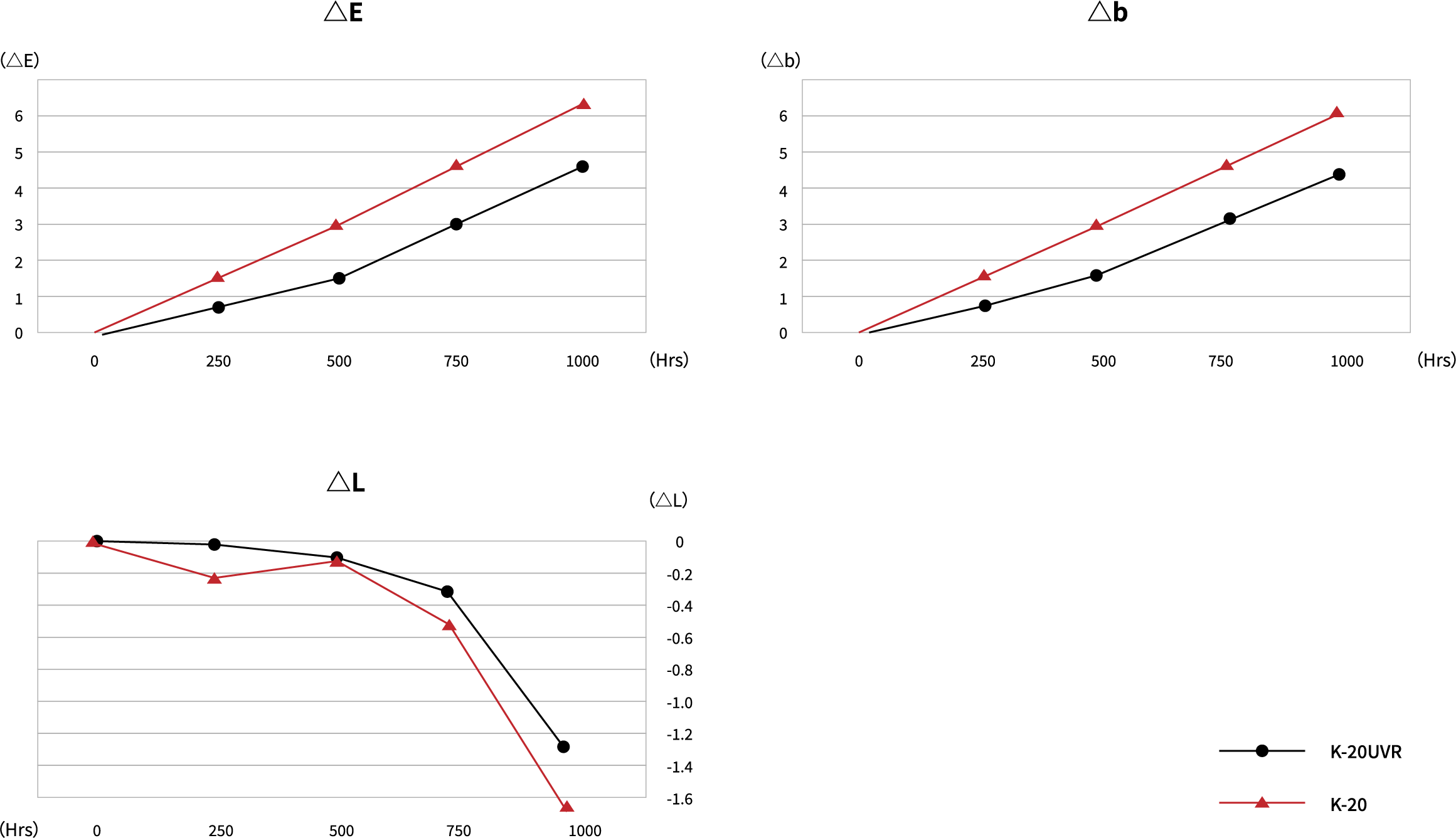
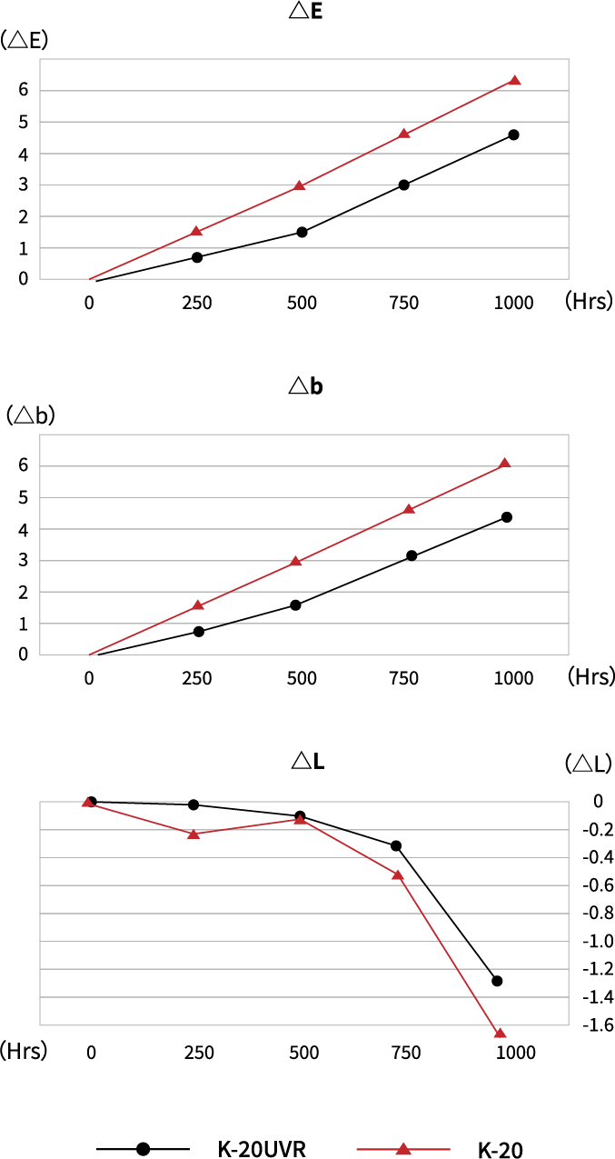
The table below shows the comparison data on K-20 vs K-20UVR in the accelerated weathering test.
Xenon Weather Meter : Suga Test Instrument XEL-7X-LHP model
Spectral Irradiance : 380
Exposure Time : 1000Hrs
Accumulated Spectral Irradiance : 136680KJ/m=380000
Black Panel Temperature : 63°
Humidity : 52%RH
Light Source/Angle : D65/10°
| 250Hrs | 500Hrs | 750Hrs | 1000Hrs | |||||||||||||
| L | a | b | △E | L | a | b | △E | L | a | b | △E | L | a | b | △E | |
| K-20UVR | 0.0 | -0.2 | -0.7 | -0.8 | -0.1 | -0.7 | 1.6 | 1.7 | -0.3 | -0.8 | 3.0 | 3.1 | -1.3 | -0.8 | 4.3 | 4.6 |
| K-20 | -0.2 | -0.5 | 1.5 | 1.5 | -0.1 | -0.9 | 2.9 | 3.0 | -0.5 | -1.1 | 4.5 | 4.6 | -1.7 | -1.1 | 6.0 | 6.3 |
Troule Shooting Guide
01. Black Specks
- 1. If a different type of the polymer had previously been used, purge it from the barrel completely.
- 2. Purge the material previously used when the molding machine is left unused over an extended time period.
- 3. Decrease nozzle temerature.
- 4. Check temperature at feed zone. Low temperatures may cause mechanical degradation, especially with high screw speed or high back pressure.
- 5. Check heater band and thermocouple location. The heater band may run at a higher temperature than the thermocouple indicates.
02. Brittleness
- 1. Dry material properly. Moisture percentage greater than 0.02% can cause a loss of properties.
- 2. Improve weld-line strength.
- 3. Decrease nozzle temerature.
- 4. Check to see if the wall thickness is constant.
- 5. Eliminate sharp corners to prevent a notch effect.
- 6. If material degradation is in doubt, lower material temperature by:
- a) Lowering cylinder temperature.
- b) Decreasing screw speed.
- c) Lowering back pressure.
03. Burn Marks
- 1. Decrease injection speed.
- 2. Decrease booster time.
- 3. Decrease injection pressure.
- 4. Check venting channels for dirts/contaminants.
- 5. Improve venting of the mold. (Add vents at burned locations)
- 6. Alter gate locations and/or increase gate sizes.
04. Discoloration
- 1. Purge heating cylinder.
- 2. Check melt temperature with a pyrometer.
- 3. Lower material temperature by:
- (a. Lowering cylinder temperature b. Decreasing screw speed c. Lowering the back pressure)
- 4. Increase back pressure to improve melt homogeneity.
- 5. Lower nozzle temperature.
- 6. Shorten overall cycle.
- 7. Check hopper and feed zones for dirts/contaminants.
- 8. Cheek for proper cooling of ram and feed zone.
- 9. Provide additional vents in the mold.
- 10. Reduce residence time.
- 11. Check hot manifold for dead spots.
05. Gloss
- 1. Increase mold temperature.
- 2. Increase melt temperature.
- 3. Increase injection speed.
- 4. Increase injection pressure.
- 5. Check surface of the mold for polish.
- 6. Clean vents.
- 7. Increase venting.
06. Jetting / Worming
- 1. Decrease injection speed.
- 2. Increase melt temperature by:
- (a. Increase cylinder and nozzle temperature b. Increase screw speed c. Increase back pressure)
- 3. Increase gate size and decrease gate land length.
- 4. Modify gate location or angle : directly into wall or pin.
- 5. Avoid gating at thick section.
07. Sink Marks
- 1. Follow rib design guidelines.
- 2. Increase injection speed and pressure.
- 3. Increase injection hold time.
- 4. Reduce melt temperature.
- 5. Reduce mold temperature.
- 6. Enlarge and/or add vents to mold parting line.
- 7. Increase size of sprue and/or runners.
- 8. Increase gate size and decrease gate land length.
- 9. Relocate gate next to heavy or thicker areas.
08. Weld lines (Knit lines)
- 1. Increase injection speed and pressure.
- 2. Increase injection hold time.
- 3. Raise mold temperature.
- 4. Raise melt temperature by increasing cylinder temperature.
- 5. Vent cavity in the weld area.
- 6. Change gate location to alter flow pattern.
09. Splay marks(Silver Streaks)
- 1. Dry resin properly.
- 2. Lower nozzle temperature.
- 3. Lower melt temperature by:
- (a. Lowering cylinder temperature b. Decreasing screw speed c. Lowering back pressure)
- 4. Decreasing injection speed.
- 5. Shorten or eliminate screw decompression.
- 6. Shorten overall cycle.
- 7. Increase sprue and runner size.
10. Sticking in cavity / core
- 1. Decrease injection pressure.
- 2. Decrease hold time and pressure.
- 3. Lower mold temperature.
- 4. Increase mold closed time.
11. Stress in part
- 1. Increase mold and melt temperature.
- 2. Decrease injection speed and pressure.
- 3. Increase gate size.
- 4. Add gates and/or relocate gates.
12. Voids
- 1. Decrease injection speed.
- 2. Increase injection hold time.
- 3. Reduce melt temperature.
- 4. Increase mold temperature.
- 5. Increase gate size and reduce gate land length.
- 6. Increase nozzle size and/or runner.
- 7. Redesign part to obtain equal wall section.
13. Warpage / part distortion
- 1. Increase injection hold time.
- 2. Increase mold closed time.
- 3. Increase mold temperature.
- 4. Check gate locations and total number of gates to reduce orientation.
- 5. Redesign part to equalize wall variation in molded part thick and thin walls.
- 6. Check cooling line layout, unbalanced cooling promotes warpage.
- 7. Increase gate size.